Start with the mating panel edges
Supply an edge drawing or a measured sample showing wire diameter, mesh geometry and the joint arrangement. Outside coil diameter, clear space and pitch all affect whether the spiral can engage the intended edges.
Products / BLASTCAGE
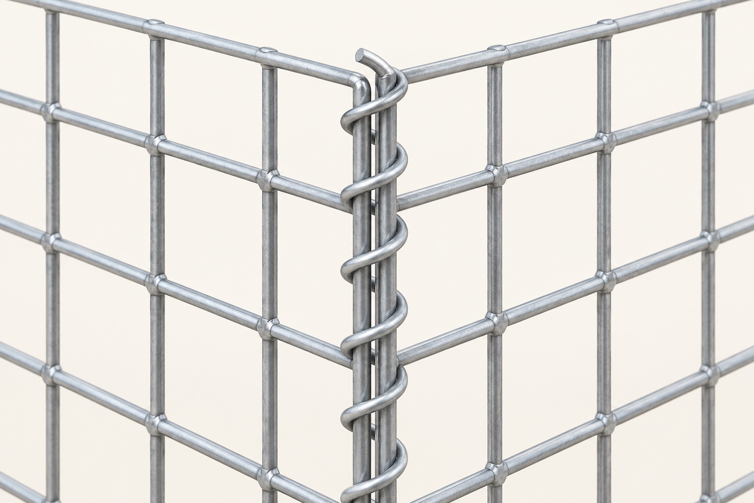
Spiral wire connectors for compatible panel edges in welded gabion and cellular mesh assemblies. Fit, quantity and installation sequence should be checked with the panels, not in isolation.
Ordering information
| Item | What to confirm |
|---|---|
| Connector geometry | Length, wire diameter, coil diameter, pitch and agreed tolerances. |
| Mating panels | Panel wire, mesh opening, edge condition and the intended number of engaged wires. |
| Joint arrangement | Corner, straight connection, lid or diaphragm joint identified on the drawing. |
| End condition | End finish and securing detail agreed for assembly and handling. |
| Surface treatment | Coating and material compatibility with the mating mesh and exposure conditions. |
| Quantity schedule | Count by connector length and joint type; list agreed spares separately. |
| Fit and packing | Sample-assembly approval if required, bundles by size and labels matching the bill of materials. |
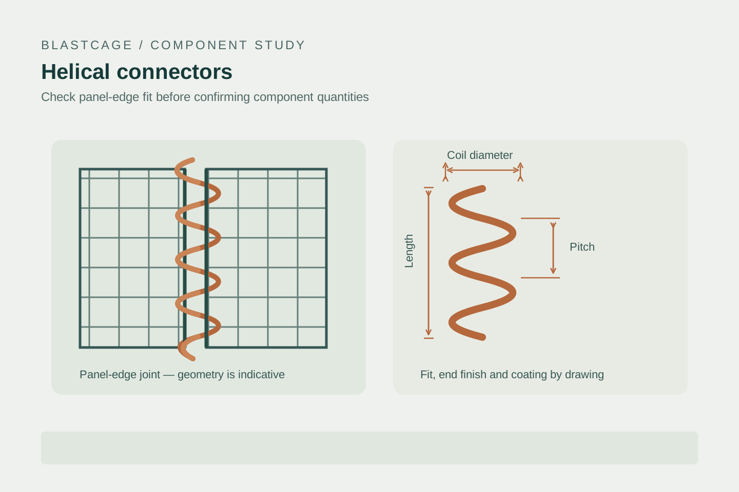
Supply an edge drawing or a measured sample showing wire diameter, mesh geometry and the joint arrangement. Outside coil diameter, clear space and pitch all affect whether the spiral can engage the intended edges.
An approved sample assembly helps reveal fit, protruding ends and installation access before a full component order. Agree how ends are finished or secured; the illustration is not an installation instruction.
Use the approved assembly drawing to count edge joints, diaphragms and spare components. A basket count alone is insufficient where adjacent cells share panels or different joint lengths are used.
A helical connector, joining pin, lacing wire and C-ring are different connection arrangements. Changes must be checked against the unit design and coating requirements; no universal interchangeability is assumed.
Have a drawing or specification?
Email it with quantities and destination. Open technical or commercial points are confirmed before an order is agreed.